The coating of pellets and granules varies from one
Pharmceutical company to the next. Before a pellet
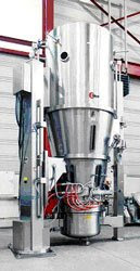
can be coated in a wurster column coater the process
must undergo cGMP. after cGMP is in placed the the
process can proceed smoothly. the product is loaded
in the wurster column with spray nozzle neatly put
in place. The filters are placed securely in the
filter house.The expansion Chamber is placed neatly
and the wurster with product is place in line with
the product bowl. when all parts are in place you
have one vertical chamber.
the equipment is then compressed to create a seal
vertical chamber.
Air-handling system
As the process air enters the fluid bed unit's air-handling system, it can be heated, cooled, humidified, dehumidified, or filtered. A typical layout of an air-conditioning system is illustrated in Figure 9.
Figure 9: A typical layout of an air conditioning system.
Figure 9: A typical layout of an air conditioning system.
Filtration: Following a bird screen, a coarse dust filter is placed where the air enters the system. Additional filtration of the air after heating is achieved by the use of high-efficiency particulate air (HEPA) filters.
Dehumidification: A cooler followed by a droplet catcher dehumidifies the air.
Heating: Process air is usually heated by a finned-tube heat exchanger. The two most widely accepted methods of controlling temperature are modulating steam valves and a face and bypass airflow damper system used in conjunction with a flooded steam coil. The face and bypass system offers the advantages of precise temperature control (+ 1 `C or less) and the ability to change temperatures rapidly during the process with little or no offset.
Humidification: During cold and dry seasons, air humidity may actually be lower than desirable, and rehumidification may be necessary. A clean-steam injector can be used for this purpose after the cold and dry air is heated. Humidification is used primarily to maintain constant inlet conditions and process times.
In many processes, when preheating is required a bypass loop can be used for preconditioned air. This loop allows the required process temperature and humidity to be attained within the vessel before the product is subjected to fluidization.
Heat and mass Transfer
In a fluidized bed, conditions for heat transfer are extremely favorable. A dry, packed bed of particles is generally a good thermal insulator because there is very little contact between adjacent particles; little heat flows by conduction, even when the thermal conductivity of the solid is high. Heat transfer by convection is also small because the motion of the interstitial gas is restricted by the particles. But in a fluidized bed, equilibrium is achieved because the particles at the wall are frequently replaced by particles from the interior of the bed. The high rate of mixing is caused by passing bubbles, which are essential to maintain heat transfer.
In the absence of a temperature probe, product temperature can be inferred. The equilibrium temperature for any surface from which water is evaporating adiabatically (i.e., without heat transfer from its surroundings) is the wet-bulb temperature. As water evaporates in the air, the dry-bulb temperature of the air falls and the humidity increases, but the heat content remains the same. In an adiabatic dryer, the wet-bulb temperature is the true temperature of the solid surface during this constant-rate period.
As in heat transfer, the maximum rate of mass transfer that occurs during drying is proportional to surface area, turbulence of the drying air, the driving force between the solid and the air, and the drying rate. Because the heat of vaporization must be supplied to evaporate the moisture, the driving force for mass transfer is the same driving force required for heat transfer, which is the temperature difference between the air and the solid.
Pressure Drop
To move air in a fluid bed, blowers or exhaust fans mounted outside of the processing area impart motion and pressure to the air using a paddle-wheel action. The moving air acquires a force or pressure component in its direction of motion because of its weight and inertia. This force is called velocity pressure and is me asured in inches or millimeters of water column (wc). In operating duct systems, a second pressure that is independent of air velocity or movement is always present. Known as static pressure, it acts equally in all directions. In exhaust systems (such as fluid beds), a negative static pressure will exist on the inlet side of the fan. Total pressure is the combination of static and velocity pressures.
Blower size is determined by calculating the pressure drops (^P) created by all the components of the completed system. For example, a 28-in. blower creates a pressure differential between the exhaust and inlet blower that is equal to the pressure at the bottom of a 28-in.-high water column.
The blower in a fluid bed system discharges directly into the atmosphere, which is designated as having a pressure of zero (gauge). Therefore, a 28-in. blower creates a ^P of 28 in. between the exhaust and inlet. However, because the exhaust has a pressure of zero, the blower has a negative pressure of 28 in. of water. The ^P created by the fan is dissipated by the equipment located in the system. Table II shows an example of the ^P experienced by various pieces of equipment in a hypothetical situation.
Equipment ^P (in. wc)
Inlet rough filter 0.5
Heater housing 0.5
HEPA filter 2
Inlet plenum & bottom plate 5
Processing material 4
Filter bags 7
Exhaust explosion protective valve 2
Air duct 0.5
Capacity for processing & exhaust air flap 6.5
Total 28
Table II
The exhaust flap dissipates excess ^P not needed to fluidize the material. This flap is controlled by a pneumatic positioner that allows an infinite number of settings. A blower with a suitable ^P will fluidize the process material properly. However, a blower without enough ^P will not allow proper fluidization of the material, resulting in a longer drying time. If the blower develops too much ^P, the control of fluidization will be very difficult. A properly sized blower should develop ^P so that the exhaust flap will be used in the 50 80% open position. When equipment such as scrubbers and duct filters is added, the ^P of the blower can be increased to compensate for the additional resistance created in the system.
Exhaust filter systems
Containing all the product inside the fluid bed system by using an exhaust air filter is one of the most important aspects of fluid bed processing. The ideal filter material should retain all of the product particles in the container while allowing process air to pass through. Cotton, polyester, polypro-pylene, nylon, and expanded polytetrafluoro-ethylene (Gore-Tex, W.L. Gore & Associates, Elkton, Maryland, USA) are the most commonly used materials. These filters can be obtained in 1- to 25-p.m sizes.
The particle size of the product being processed and the type of unit operation (coating, agglomerating, or drying) will dictate the level of porosity of the filter material that should be used. Because the filter can cause a significant ^P, many process failures result from the selection of filter media that have openings of the wrong size.
Process failure can also occur when the filter clogs because of excessive fluidization of fine powder or when filters are improperly cleaned during the process. Too fine a filter will impede fluidization, causing excessive ^P, and a too-coarse filter will cause loss of valuable product carried by process air. Maintaining a large filter area ensures proper airflow and reduces ^P due to impingement from overfluidization. Reduced-area or pleated filter media can be problematic, because the ^P across the filter bag can increase with air speed.
Process considerations
Airflow in drying: One constraint in using a fluid bed dryer is the inability to achieve uniform fluidization. An indication of good fluidization is a free downward flow of the granulation at the sight glass of the drying bowl, but such limited observation could be misleading. It is possible to detect this situation by monitoring the outlet-air temperature. Every product has a unique constant rate of drying period in which the bed temperature remains relatively constant for a significant length of time. Therefore, if the outlet-air temperature rises more rapidly than anticipated, it is an indication that fluidization is incomplete. In this case, the process must be stopped, the granulation stirred to distribute the moist material, and the process restarted.
Airflow in granulation: While the granulating solution is being sprayed, the exhaust flap is controlled to achieve proper fluidization. The objective of this process is to fluidize the powder for maximum exposure to the spray nozzle. Whereas overfluidization may produce uneven or lumpy agglomerates and may also cause filter plugging, underfluidization may stall the bed and ultimately lead to bed collapse. Filters can also become plugged.
Minimum fluidization velocity depends on particle size' and particle humidity.4 As both change during the granulation process, it is necessary to vary the air velocity to maintain uniform fluidization. As the product dries, its density changes and less airflow is required.
The difference between the temperatures of the drying air and the product surface is expressed as ^T. It is necessary to distinguish between ^T in the granulation phase (^T"") and ^T in the drying phase. Gran- ule size is directly proportional to the moisture content of the bed in the granulation phase. ^ gran primarily affects granule growth. As the value of ^T is increased, drying time is decreased. Variations in inlet-air humidity thus affect the granule size by either increasing or decreasing ^Tgranas the drying capacity of the air changes. This influence can be eliminated by keeping the difference (^T) between the inlet-air temperature and the wet-bulb temperature constant.
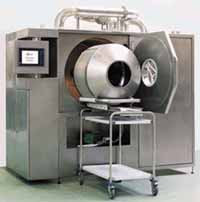
Airflow in coating: Tablet, pellet, and particle coating are all performed in fluid bed equipment using a top spray, a bottom spray with a Wurster column, or a rotary coater. The coating process involves the deposition of droplets on the substrate material, followed by spreading and coalescing of the droplets, which form a continuous layer as they adhere to the matrix. Throughout the process, solvent is evaporating. It would be impossible to dry any more solvent than the drying air can accept or to dry any faster than the solvent can be heated to its vapor-transi-tion temperature. In a system with good product turnover and proper exposure to spray, the one remaining requirement for successful coating is the drying system. If water is present in the organic solvent solution and dew points are not controlled, then the drying capacity varies, and the driving force for the evaporation of water is affected. It is advisable to control ambient air dew points in organic solvent processes and in aqueous coating operation.
Conclusion
The fluidized-bed unit is one of the most versatile pieces of Pharmaceutical
and food processing system.
skip to main |
skip to sidebar
Black Caribe

Black Caribe
Black Caribe
About Me

CLICKBANK VENTRICLE
THE CLICKBANK VENTICLE
MAKE $379.66 EVERYDAY OF THE WEEK.
CHANGE YOUR LIFE WITH CLICKBANK VENTRICLE.
JUST LIKE THE LEFT VENTRICLE PUMP OXYGENATED BLOOD
TO ALL LIVING CELLS OF YOUR BODY
CLICK BANK VENTRICLE DOES THE SAME.
THE SECRET IS GETTING THE PRODUCT TO THE
CUSTOMER WITH GREAT SATISFACTION
THE VENTRICLE IS LIKE THE RAILWAY LINE
NO STOP SIGN UNTIL THE TRAIN STATIONED.
ALL EXPRESS TO THE CUSTOMER.
GET THE CLICKBANK VENTRICLES.
http://6707cvqjv31hdq6xwjm5mdppz9.hop.clickbank.net/?tid=WRS45
http://a11b4sycxcsh5162wjn3my1w53.hop.clickbank.net/?tid=WRS45
http://cb59fskfq8rkko4o-7w5mceh1i.hop.clickbank.net/?tid=WRS45
Click Here!
Click Here!
Click Here!
$379.66 Daily.
CLICKBANK VENTRICLE
CHANGING LIFE EVERYDAY.
Search This Blog
Wurster Column Coating
Black Caribe
Wurster Column Coating
Black Caribe
Followers
BIG FISH DATA COLLECTION
| |||||||||||||
| |||||||||||||
| |||||||||||||
| |||||||||||||
| > | |||||||||||||
| |||||||||||||
New Coating Technique for Tablets
From Solvent to Aqueous Film Coating
Suresh Pareek & Chetan Raj Sharad
Since ages tablets / pills has been the most preferred dosage form to deliver any medically active substance to human body.
These tablets/ pills have to be coated for various reasons using a wide variety of materials and processes. The majority of tablets are coated for cosmetic reasons and for identifi-cation of specific brand in market place, however, a number of products are now coated to provide some functional benefits like enteric coating, moisture protective coating, coatings for control release, flavour coating, taste mask coating etc.
Until about 1950, sugar was the first choice as coating agent for pharmaceutical preparations and much time and efforts were spent in perfecting the sugar coating techniques. Nobody ever was concerned about the problems like material cost, toxic effects due to coating or pollution etc. because the solvent used was always water. How- ever, sugar coating technique was time consuming, affecting the productivity and the quality of finished product was dependent on the skills of operator. Many a times the companies had to reschedule their production plans due to the non-availability of skillful coating operator. These problems led to the development of film coating technique which was mainly based on solutions of different polymers in various organic solvents. All these solvents are toxic in nature. As the level of understanding regarding the toxic effects of these solvents is increasing, industrial hygiene rules and FDA regulations are being tightened world over, limiting the use of these solvents and exposure of workers to these solvents. Another area of concern is the cost of these solvents, which can only be expected to increase in coming times. In today's competitive business environment any cost saved will improve the market viability and success of any product. We are, therefore, left with no other choice but to eliminate the use of organic solvents and start using water as the solvent system for tablet coating. Like any other system, aqueous film coating has some disadvantages. The main reason for using organicsolvents was to avoid possible decomposition of active ingredients and many other process related problems such as over wetting, picking and sticking etc. which may occur with aqueous coating systems. However, research and experience of industry has indicated that the decomposition of active ingredients and possible coating difficulties are not so serious issues in actual applications and all such problems can be sorted out by scientific evaluation of the reasons for these problems. Most of these problems could be categorized as :
1) Material related problems
2) Coating instrument related problems
3) Coating process related problems
In this article we will discuss various issues related to Materials used for Aqueous Film Coating.
A large number of problems observed during conversion from organic solvent based coating to aqueous film coating are related to material selected for coating formulation. Some of these problems could be :
a) Poor film adhesion
b) Poor tablet finish due to high viscosity of coating solution
c) Uneven surface of finish product
d) Non-uniform colour of finished product
e) Longer coating cycle time
To understand these coating problems, we will have to understand the properties and role of various materials used in film coating formulations.
Polymers
As the tablet coating technique was changed from sugar coating to film coating, polymers like methyl cellulose, hydroxypropyl methylcellulose, ethyl cellulose etc. became the main coating materials in place of sugar. The higher viscosity grades of HPMC though provided film with good tensile strength but produces films having poor adhesion with the core surface and very often one can easily peal-off the film from the tablet surface. The same HPMC when dissolved in water give rise to many other problems like -
high solution viscosity
water is a poor solvent for HPMC as compared to organic solvents, therefore, solution preparation is difficult
water has much higher surface tension than organic solvents, material wetting is difficult resulting in poor film adhesion
films produced using water as solvent has poor mechanical proper- ties like low tensile strength, higher modulus of elasticity and low film adhesion.
Therefore, the selection of correct polymer system is very critical for the success of aqueous coating formulation. By selecting the lower viscosity polymers, the solid content in the coating formulation can be increased which will result in lesser amount of water required which in turn can increase the coating speed. However, the lower viscosity HPMC produces the films with lower tensile strength. As described earlier the film produced by HPMC using water as solvent system may have poor film adhesion resulting in easy peel-off from the tablet surface. To overcome this problem some formulators have used the combination of HPMC and HPC. HPC provides better film adhesion to the substrate then HPMC, however, other mechanical properties of HPC are not comparable to HPMC, moreover, the cost of HPC is much higher then HPMC and thus makes the formulation economically non-viable. Various other polymers are also used in developing aqueous film coating formulations like Sod. CMC, PVA, PVP, Sod. Alginate, PEG etc. either alone or in combination.
Plastisizers
The next most important component of the coating formulation is plasticizer. A wide range of plasticizers are available to the formulator such as phthalate esters, phos-phate esters, other esters like citrates, stearates, sebacate, oleate, adipate etc. oils, glycerol, glycols etc. The important factors to be considered here are :
- Water solubility of the plasticizer : Hydrophobic plasticizers will create problems in solution preparation and can affect the D.T. and dis- solution profile of the finished product.
- Water vapour transmission rate through the film : Higher concentration of plasticizer in the film generally tends to increase the water vapour permeability.
Concentration in the coating formulation :
Higher concentration of plasticizer reduces the modulus of elasticity (a desired effect) and thus reduces the possibility of logo bridging but also reduces the tensile strength of the film (undesired effect).
- Film adhesion generally tends to increase with increased concen tration of plasticizer.
- Higher concentration of plasticizer can lead to its bleeding (making the tablet surface feel oily).
- in most of the cases presence of plasticizer improves the gloss level in the finished product (depending on the quality and concentration of the plasticizer).
- Volatility of the plasticizer : Aqueous coating generally need higher drying capacity during the coating cycle due to less volatility of water, if the plasticizer is more volatile e.g. propylene glycol, much of the plasticizer may get lost during the coating process.
Therefore, one needs to strike a balance between the desired and undesired effects of the plasticizer and optimize its concentration in the coating formulation. Many a times use of combination of plasticizer becomes necessary to achieve the most optimum results.
Additives
The properties and composition of other components of the film coating formulation also need to be considered and optimized to get the most desired effects without affecting the quality of the film. Various other components which could be used in coating formulation are -
- Pigments
- Opacifier
- Anti-tacking agent
- Film adhesion enhancer
- Sweetners
- Flavours
- Anti foaming agent
The concentration and the properties of each of these excipients can affect the quality of the resulting film, e.g.
- The commonly used colourants in sugar coating are water soluble dyes. However, the overall colour effect of these dyes depend on the dye concentration at a particular point, thickness of film at that point and the residual moisture content in the film at that point. As these parameters can differ from tablet to tablet, the colour difference among various tablets within the same batch may become very visible.
- The opacity of the film depends on the difference between the refractive index of the polymer and other components of the coating formu- lation. The lake colours used in film coating has refractive index similar to that of various polymers, thus the opacity of lake colours is very poor.
- The most commonly used anti- tacking agent is Talc, which if used in higher concentration tends to settle down from the coating suspension, thus affecting the composition of suspension during the coating process. Further, it is poor opacifier and tends to produce translucent films.
- As the aqueous film coating need higher drying capacity, the volatile matter in the flavours used may get lost, changing the nature of the flavour. These volatile matters may also interact with other components of the coating formulation and can affect their properties. One, there- fore, need to use specific flavours and incorporate them in the coating formulation in such a manner so that it does not affect the film quality.
It, therefore, once again becomes a lot of balancing act while developing the optimized coating formulation.
Effect of Residual Moisture
One should keep in mind that water is less volatile than organic solvents, and will require much better drying capacity resulting in higher energy cost to the coating process. However, exceptions do exist in optimized film coating formulations which have a very low affinity for water, and therefore, can be run at lower temperatures, higher spray rates. Ideal Cures Pvt. Ltd. has developed few such products (under INSTACOAT range of products) which dries faster and the whole coating process can be completed in the same or sometimes little less time as compared to organic solvent based coatings.
The use of organic solvents raises the possibility of residual solvent in the finish product which is increasingly becoming a concern to the regulatory agencies due to their adverse effects on the consumer health.
Glatt Coated
Glatt Master
http://www.blueprintaffiliates.com/products.html
http://cbtopsites.com/r/tohayle45
http://cbtopsites.com/r/tohayle45
Hello glatt
Glatt
Wurster Column Coating
Black Caribe